Atari mini Trakball opto repair |
Post Reply 
|
| Author | |
DaveSpicer 
Kill Screen 
Joined: 10 September 2009 Location: Cornwall Status: Offline Points: 2855 |
 Post Options Post Options
") Thanks(0) Thanks(0)
 Quote Reply Quote Reply
 Topic: Atari mini Trakball opto repair Topic: Atari mini Trakball opto repairPosted: 04 October 2010 at 11:40pm |
|
Thought this might be of use to anyone with a busted mini Trakball, as used on the cocktail version of Missile Command and others.
One of the Trakballs on my MC has been very erratic since I bought it. Symptoms were direction changes on-screen even when the ball was continually moved in one direction. Both x and y were affected. The problem was tracked down to the 2 optical encoder boards. Each board has two infra red transmitters and receivers inside a black, plastic enclosure: 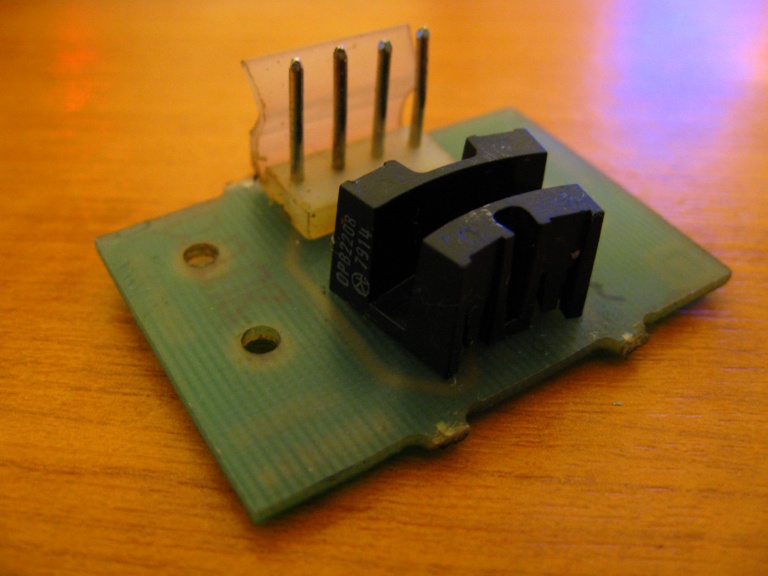 While the enclosure may look like an all-in-one custom part, it isn't and its innards can be replaced. Drop in replacement parts can be found at Maplin - see part numbers CH10L and CH11M. Here they are: 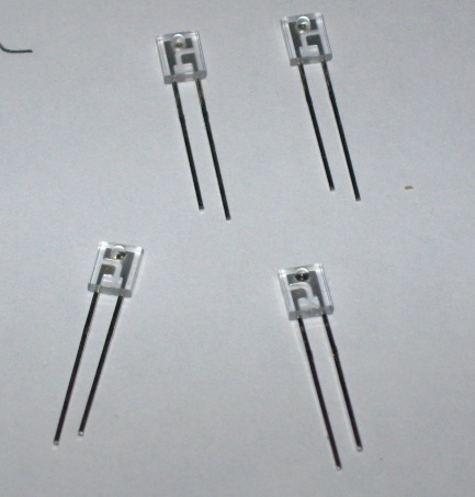 Unsolder the 8 legs from the board and remove the optical switch enclosure. Looking at the base, you'll see that the rx/tx parts are slotted into holes with a small plastic clip preventing them from being pulled out. Now the tricky bit: the clip needs to be held aside just far enough to allow the part behind it to be yanked out by the legs. I did this by getting a thumbnail behind the clip to hold it back while grabbing the legs with a pair of pliers held in the other hand. Get it wrong and you'll be pulling component legs off at this point! Don't panic: you'll almost always get 4 attempts as the first break usually leaves a stump which you can still grab onto. Once down to the last stump, snapping the clip off would probably be safer than taking the risk of not being able to remove the part. One receiver removed: 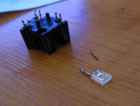 Got 'em all: 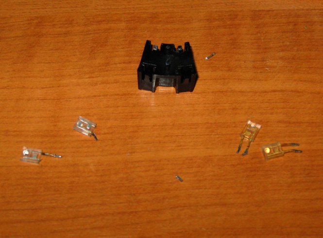 Now slot the new parts in. The receivers connect to the outer pins on the board's connector and live inside the smallest part of the enclosure: 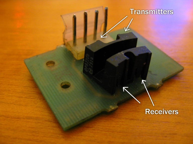 Make sure the components are inserted the right way around with the raised 'bobble' on each facing towards the middle of the enclosure. There are grooves on each hole, so it would take a determined effort to put one in back-to-front. 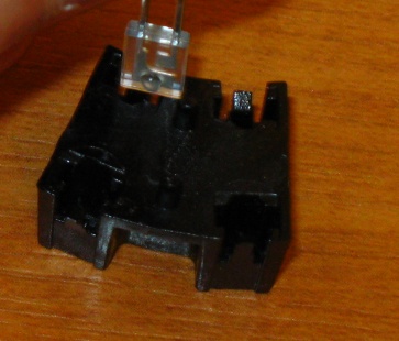 The transmitters should have red dots on the back of the legs. Alternatively, when the parts are held with the raised part facing towards you and the legs pointing down, the right leg of the transmitter is longer than the left. All parts in situ:  Make sure the parts are pushed down far enough for the clips to pop back into place. Now solder the assembled enclosure back onto the PCB and pop it back in the game for testing. After surgery, my Missile Command Trakball was as good as new. -- Dave Edited by DaveSpicer - 05 October 2010 at 7:37pm |
|
 |
|
|
river9999uk
Kill Screen
A sledge hammer is a repair tool Joined: 26 July 2005 Location: Devon Status: Offline Points: 5762 
|
Post Options
Thanks(0)
Quote Reply
Posted: 05 October 2010 at 6:47pm |
|
Nice one dave and great descriptions and pics! A+++
Edited by river9999uk - 05 October 2010 at 6:47pm |
|
|
"You have two objectives. Avoid their tracking systems and find your re-fueling point."
|
|
|
|
|
PAC-MAN
Kill Screen
Joined: 23 December 2005 Location: UK Status: Offline Points: 2339 |
Post Options
Thanks(0)
Quote Reply
Posted: 05 October 2010 at 7:03pm |
|
Nice one!! very handy
|
|
|
|
|
Goose Green
Level Up 

Joined: 19 April 2005 Location: London Status: Offline Points: 236 |
Post Options
Thanks(0)
Quote Reply
Posted: 06 October 2010 at 4:35pm |
|
Excellent post, I have a couple of these that need repairing. Cheers
|
|
|
I will make no soup.
|
|
|
|
|
Nukem
Admin 

Joined: 21 September 2007 Location: UK Status: Offline Points: 17306
|
Post Options
Thanks(0)
Quote Reply
Posted: 06 October 2010 at 5:40pm |
|
Top post Mr Spicer :)
Edit: Opps should not be posting messages in repair logs, Shhhhhhhhhhh I think we will get away with it Edited by Aran - 06 October 2010 at 5:42pm |
|
|
Buy & Sell retro (and modern) games & consoles? Join us --> Click Here
|
|
|
|
|
john bud
Moderator 
JB Mobility Scooters Joined: 08 February 2009 Location: Scotland Lanarkshire Status: Offline Points: 7123 |
Post Options
Thanks(0)
Quote Reply
Posted: 28 October 2010 at 6:53pm |
|
a quick question if i may.
assuming all sizes of trackball work the same. is it fair to say these parts will also, fit all trackballs ??? i have a similar fault except the x always goes left even when trying for right. i managed to get a roller kit thanks tbliley so im now thinking in for a penny. would it be the same on an upright ??? any advice would be great. cheers. john bud
|
|
|
god my fingers ache
|
|
|
|
|
DaveSpicer
Kill Screen
Joined: 10 September 2009 Location: Cornwall Status: Offline Points: 2855 |
Post Options
Thanks(0)
Quote Reply
Posted: 28 October 2010 at 7:54pm |
|
There may be some variation. Not sure about trackballs, but I've seen mice with opto-couplers which have one receiver and one transmitter molded into a single, U-shaped part. I think the upright Missile Command uses the same board as above, in which case off to Maplin...
Any trackball with opto couplers in it could be repaired by sticking the seperate parts directly on the board as long as you get the polarity right. Worst case, the resistor on the LED side may need changing if the current rating is different on the replacement parts. Having the enclosure presumably helps to cut out ambient light and makes sure the parts are positioned properly. Assuming you have the same opto board as above, you can do some simple tests to track down problems: 1) Check the resistance between the ground and outer pins on the opto board with everything wired in, but the game off. With the connector at the back of the board, the ground is the left-hand one of the center 2 pins. You should see 3.3K on a Missile Command. If not, start pulling things apart and testing step by step to find a short, duff connection or bad resistor. 2) If step 1 was ok, turn on the game and monitor the voltage on each of the outer pins of the opto board in turn. You should be able to make both pins change between 0 and close to 5 volts by slowly turning the appropriate roller. If you can't, there's probably an IR LED or receiver fault and you need to swap the parts out. Might as well do the lot while you're there rather than trying to fault find any further. -- Dave Edited by DaveSpicer - 28 October 2010 at 7:59pm |
|
|
|
|
Level42
Bonus Stage 
Joined: 03 February 2007 Location: Netherlands Status: Offline Points: 318 |
Post Options
Thanks(0)
Quote Reply
Posted: 20 February 2011 at 10:26am |
|
Great !!! I've always wondered if this was possible at all !
Thanks for the excellent description and pics. Do you know the make and model of the IR LED and photo-receiver ? The Maplin site doesn't list this. I'd prefer to order with RS-online because they have 0 shipping costs. Hope to find the same (or an equivalent) on RS's site....
|
|
|
|
|
Level42
Bonus Stage
Joined: 03 February 2007 Location: Netherlands Status: Offline Points: 318 |
Post Options
Thanks(0)
Quote Reply
Posted: 20 February 2011 at 10:54am |
|
I think these might work ?
http://nl.rs-online.com/web/search/searchBrowseAction.html?method=getProduct&R=6549179 http://nl.rs-online.com/web/search/searchBrowseAction.html?method=searchProducts&searchTerm=lpt80A&x=0&y=0
|
|
|
|
|
Level42
Bonus Stage
Joined: 03 February 2007 Location: Netherlands Status: Offline Points: 318 |
Post Options
Thanks(0)
Quote Reply
Posted: 21 February 2011 at 10:59pm |
|
I've just been trying this for over an hour and all I end up with is broken legs....the opto's really seem to be glued in there ! ....please help ?
I wonder if simply soldering a pair of those opto/receiver combo's straight on the PCB would simply work....what it the housing doing anyway ? I can think of: -Ligning out the sets too each other (not too critical) -filtering out ambient light, but when the opto board is in the machine (under the CP, not much light getting in there....)
Edited by Level42 - 21 February 2011 at 11:00pm |
|
|
|
|
DaveSpicer
Kill Screen
Joined: 10 September 2009 Location: Cornwall Status: Offline Points: 2855 |
Post Options
Thanks(0)
Quote Reply
Posted: 22 February 2011 at 1:33am |
|
The key is keep the clip clear of the opto part and pull firmly but slowly. They fit very snugly and at first I did wonder whether they were glued in. Something else you could try is screwing a long, small-diameter self-tapper into the clear casing to give a firm anchor point.
The housing keeps the optos nicely aligned and, as you said, probably helps to cut out ambient light. They ought to work just fine if put straight on the board and I've seen old ball mice done this way. I'll have to have a better look at the parts you quoted tomorrow. The transmitter has the same If as the Maplin ones, so ought to be okay. The forward current is easily tweaked by changing the resistor on the opto board if need be. -- Dave |
|
|
|
|
Level42
Bonus Stage
Joined: 03 February 2007 Location: Netherlands Status: Offline Points: 318 |
Post Options
Thanks(0)
Quote Reply
Posted: 04 March 2011 at 10:30pm |
|
Hi Dave, do you think the mentioned types will work ?
I'm ready to give it a try...
|
|
|
|
|
DaveSpicer
Kill Screen
Joined: 10 September 2009 Location: Cornwall Status: Offline Points: 2855 |
Post Options
Thanks(0)
Quote Reply
Posted: 05 March 2011 at 2:34am |
|
Hi,
Hmmm, forgot about this, sorry. My previous post didn't involve an engaged brain because the max If value is pretty much irrelevant unless it's unexpectedly small. The datasheets aren't amazingly helpful for those parts, lacking any guidance as to typical values. However, I'd be inclined to try them as you can easily tweak the brightness. The legs do appear to be the right way around, although be aware that the receiver has the long/short legs switched when compared to my parts pictured earlier. Make sure you have some way to tell them apart before removing the packaging! Suggested course of action based on thinking about it a bit: (background info in a followup post so as not to get bogged down) - Swap the parts in. - Monitor the outputs from the opto board with the game plugged in and powered. - If you can shield the board as much as possible, you should see 3.3-5 volts and close to zero volts as you turn the rollers by hand. The game will do *something* if the difference between the two is at least 2 volts or so, but the results may be erratic. Possible failures... Output stuck at zero probably means the transmitter/receiver are back to front (or I was mistaken about the leg order). "On" voltage too low could be a bad connection or insufficient transmitter brightness. Power down and test the resistance from the outputs to ground on the PCB. You should see 3.3K on a Missile Command, not sure about others. Waggle the loom and connectors to make sure you can't make the value change. On mine the opto connectors were really loose and I bent the pins a little to make a more solid connection. Also check that you have a good 5 volts at the board. Assuming these checks didn't find anything, you could decrease the value of the resistor on the opto board to increase the transmitter brightness. Temporarily holding/clipping another 100 ohms in parallel will double the forward current and would be a good first step to see if it makes any difference. -- Dave [Edited to fix 'transmitter/emitter'.. should have said 'transmitter/receiver'] Edited by DaveSpicer - 07 March 2011 at 9:01pm |
|
|
|
|
DaveSpicer
Kill Screen
Joined: 10 September 2009 Location: Cornwall Status: Offline Points: 2855 |
Post Options
Thanks(0)
Quote Reply
Posted: 05 March 2011 at 2:45am |
|
As promised (or threatened), some background info. I reserve the right to be completely wrong about any or all of it...
 The opto board powers the 2 transmitters in series with a 100 ohm resistor to limit the current. Assuming a voltage drop of 1.5V on each transmitter (typical for IR LEDs), the forward current is 5 volts - 2*1.5 volts / 100 ohms = 20 mA. Scanning a variety of IR LED datasheets, the 20mA figure comes up as "typical" when a figure is given. Pretty much the same as standard LEDs where anything between 10mA and 20mA is damn near full brightness. I gave some misinformation in an earlier post when I said the opto outputs should be near 5 volts. The H22A1 is quoted as a compatible assembly and its datasheet gives a minimum "on" current of 1mA at the receiver when the transmitter current is 20mA. Outputs go to ground through 3.3K ohms on a Missile Command board, giving a minimum voltage @1mA of 3.3 volts. Anything lower would suggest something's on the way out, even if the trackball seems to be working. The receivers I used gave a much higher "on" current and came damn near to getting the output all the way up to 5 volts. -- Dave [Edited to refer to the LEDs as 'transmitters' rather than 'emitters' to avoid possible confusion] Edited by DaveSpicer - 07 March 2011 at 8:57pm |
|
|
|
|
Level42
Bonus Stage
Joined: 03 February 2007 Location: Netherlands Status: Offline Points: 318 |
Post Options
Thanks(0)
Quote Reply
Posted: 07 March 2011 at 8:26pm |
|
Excellent info Dave, thanks !!!
I'll just order a couple and give it a try. In the mean time I received some replacement boards from the US. Interesting enough there were also two wico boards in there. These have a schmitt-trigger IC on board (I think the Centi has them on the game PCB) but still work electrically (same pins and connector) However the boards are bit smaller and won't fit in a Atari housing. So, I figured I might be able to solder the opto's themselves over to the Atari boards. They were two single transmitter/opto combo's next to eachother. However, I looked at the board traces and turns out the emitter and collector are reversed on these opto's, which rules out direct "transplantation". Although the problem is now solved with some of the spare boards, I'd still like to repair the bad one's I have now so I will give it a try and report back here. |
|
|
|
|
DaveSpicer
Kill Screen
Joined: 10 September 2009 Location: Cornwall Status: Offline Points: 2855 |
Post Options
Thanks(0)
Quote Reply
Posted: 07 March 2011 at 9:01pm |
|
No probs. It'll be good to hear how you get on.
I started mixing up terms in the posts above and have edited to fix. Probably something to do with posting in the early hours. ;-) -- Dave |
|
|
|
|
smarty
Bonus Stage

Joined: 09 November 2004 Location: Hampshire Status: Offline Points: 430 |
Post Options
Thanks(0)
Quote Reply
Posted: 19 October 2014 at 4:22pm |
|
A quick bump for this old thread as it helped me out today... After telling someone I only had one game down at the moment, during a game on Centipede this afternoon the up/down motion of the trackball stopped working. Doh! A google search pointed me back here, I removed the Optos from the boards and found I had one faulty receiver when comparing it to the other working one, after quick trip to Maplin and a bit of soldering Centi's working fine again. The Maplin part numbers are still current, if you're lucky they may have one of each in stock!
Cheers to Dave for the original post.
 Edited by smarty - 19 October 2014 at 4:23pm |
|
|
|
|
Post Reply
|
|
 Tweet
Tweet
|
| Forum Jump | Forum Permissions You cannot post new topics in this forum You cannot reply to topics in this forum You cannot delete your posts in this forum You cannot edit your posts in this forum You cannot create polls in this forum You cannot vote in polls in this forum |


 Topic Options